- Dc Motor Control Circuits
- Diy Dc Motor Driver Circuits
- Dc Motor Driver Circuits
- Dc Motor Drive Circuit
- Dc Motor Driver Ic
Definition: The DC motor drive is a type of amplifier or power modulator that integrate between the controller and a DC motor. It takes the low current and then converts it into a high current which is appropriate for the motor. The DC motor drive also provides the high current torque, 400 % more than the rated continuous torque. The important applications of DC motor drives are rolling mills, paper mills, mine winders, hoists, machine tools, traction, printing presses, textile mills, excavators and crane.
Types of DC Motor Drives
- Non-regenerative DC Drive – This drive rotates only in one direction and hence also called single quadrant drive.The non-regenerative DC motor drive does not have any inherent braking capability. The motor is terminated only by removing the supply. Such type of drive is used in a placed where high friction load or strong natural brake requires.
- Regenerative DC Drive – It is a four quadrant drive, and it controls the speed, direction and torque of a motor. Under the braking condition, this drive converts mechanical energy and load into electrical energy which is returned to the power source.
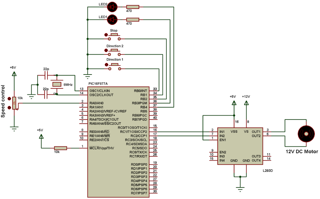
The circuit of bidirectional DC motor driver under fairly simple and is built with a voltage comparator circuit Op-Amp IC 741 and a pair of NPN and PNP transistor driver. The circuit of bidirectional DC motor driver in the figure below can work with a symmetric voltage source ± 9 volts and 6-9 volt DC motor loads. The motor driver IC is an integrated circuit chip used as a motor controlling device in autonomous robots and embedded circuits. L293D and ULN2003 are the most commonly used motor Driver IC that is used in simple robots and RC cars. Brushless DC motor (BLDC) and permanent magnet AC synchronous motors drives have many advantages such as high efficiency, small size, less rotor losses, and fast torque response over the induction motor drives. Therefore, this chapter will focus on the design and implementation of a motor drive as well as its realization of control algorithm. DC Relay Driver Circuit. We will first go over how to build a relay driver circuit for relays which operate from DC power. To drive a DC relay, all we need is sufficient DC voltage which the relay is rated for and a zener diode. All relays come with a voltage rating. This is called on a relay's datasheet its rated coil voltage.
Braking of DC Motor Drives
The braking is the phenomenon of reducing the speed of the DC motor drive. In braking, the DC motor drive works as a generator. It develops the negative sequence torque, which opposes the motion of the drive. The braking of the DC motor drive is mainly classified into three types. i.e., regenerative braking, dynamic braking and plugging.
Regenerative Braking
In regenerative braking, the generated energy is supplied by the source. For regenerative breaking following condition should be satisfied.
E > V and negative Ia.
The regenerative braking is possible only when the speed of the rotor is more than the rated speed. The speed torque characteristic for a separately excited motor is shown in the figure below. The regenerative braking is only possible when the capacity of the load is less than the regenerated power, and all the regenerated power will not absorb by the load.
Dynamic Braking
In dynamic braking, the rotation of the arm causes braking. The motor armature disconnects from the source and connects across a resistance. The figure of a separately excited DC series motor is shown in the figure below.
Dc Motor Control Circuits
The series machine works as a self-excited generator, and the field connection reverses so that the field assist the residual magnetism. The curve shown below shows the speed torque curve and transition from motoring to braking.
Plugging
In plugging the braking is done by reversing the supply voltage of a separately excited motor. So that, the motor assists the back emf in forcing armature current in the reverse direction. Resistance is also connected in series with the armature to limit the current.The plugging gives fast braking as compared to generative and dynamic braking.

Speed Control Methods of DC Motor Drives
Diy Dc Motor Driver Circuits
The speed of the DC motor drives can be control by any of the following methods.

Armature Voltage Control

This method prefers because it has high efficiency, good transient response and good speed regulation. It provides speed control only below the rated speed because the armature voltage cannot be allowed to exceed the rated value.
Field Flux Control
This method is used for controlling the speed above the rated value. Normally, the maximum speed of the motor is twice the rated speed, and in the special motor, it is six times the rated speed.
Dc Motor Driver Circuits
Armature Resistance Control
In this method, the speed is varied by wasting power in external resistor that is connected in series with the armature. This method is mainly used in alternate load application where the duration of low-speed operation forms only a small portion of the total running time.
Dc Motor Drive Circuit
Armature voltage control has replaced this method in various applications.
Dc Motor Driver Ic
Related terms:
